Spacing Guide
Layout and Spacing
Tubing and Ultra-Fin spacing guide — match fin density to the calculated heat load, keep loops balanced and design for the lowest practical water temperature.

HEAT LOAD OPTIMISATION

JOIST SPACING VARIATIONS

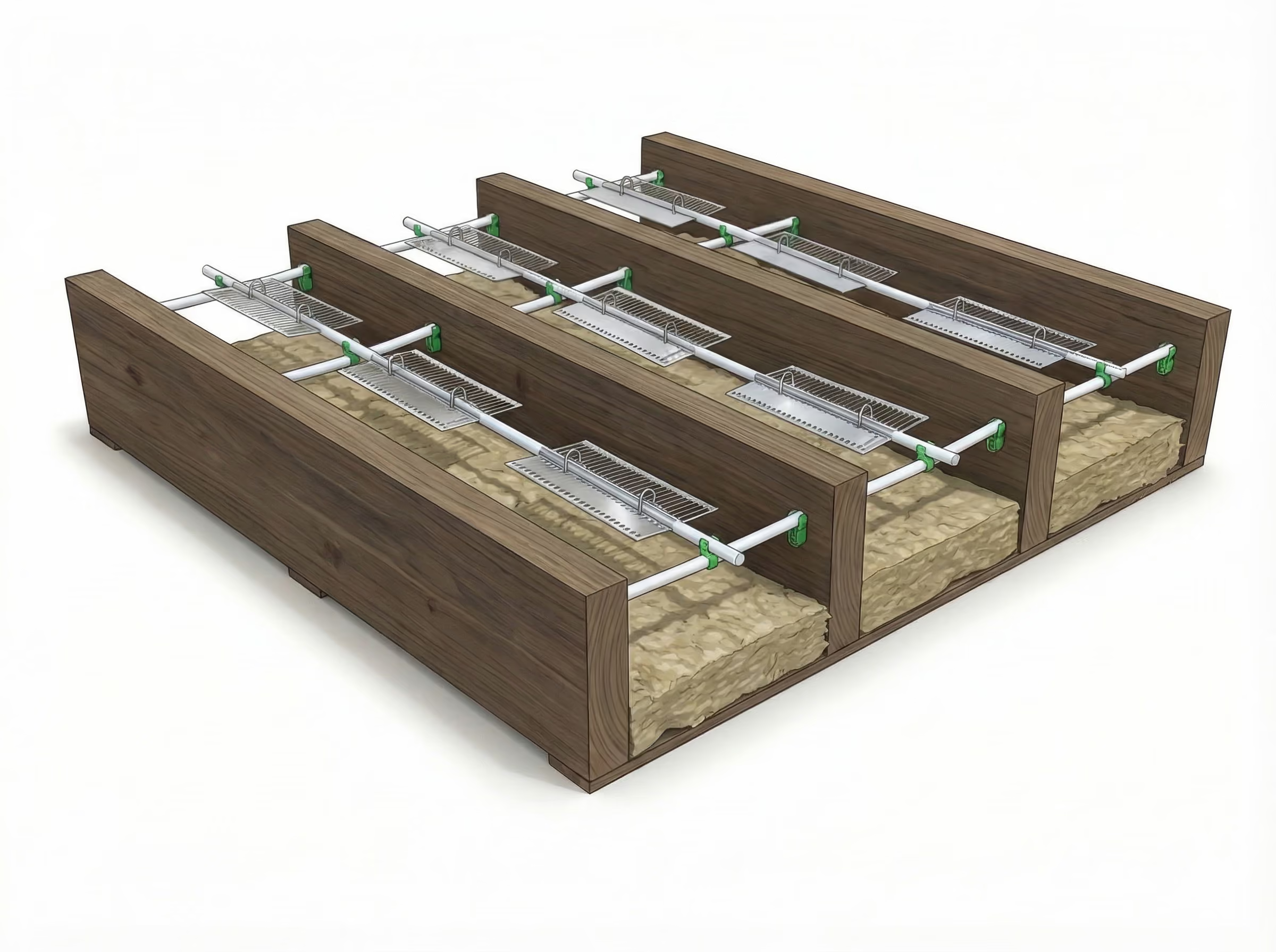
TUBING & UF PLACEMENT

INSTALLATION COORDINATION
Spacing and Heat Load
Density follows the load
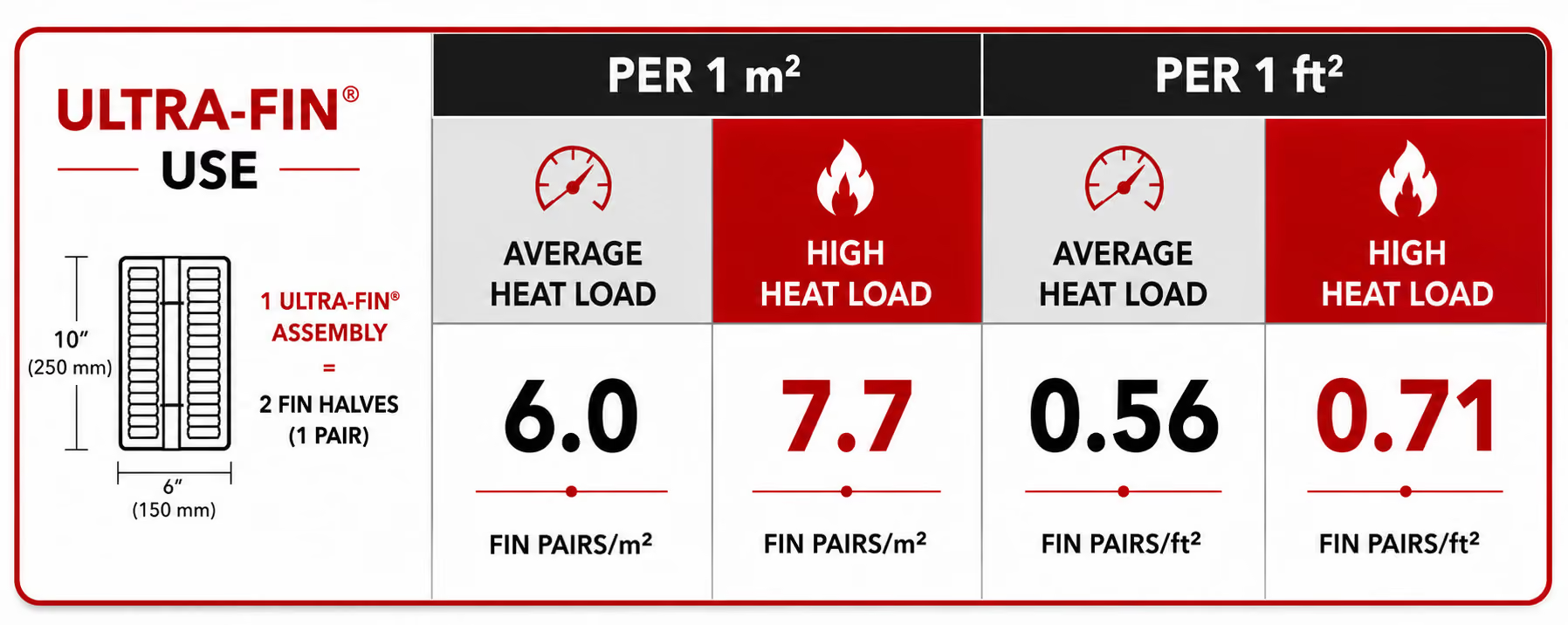
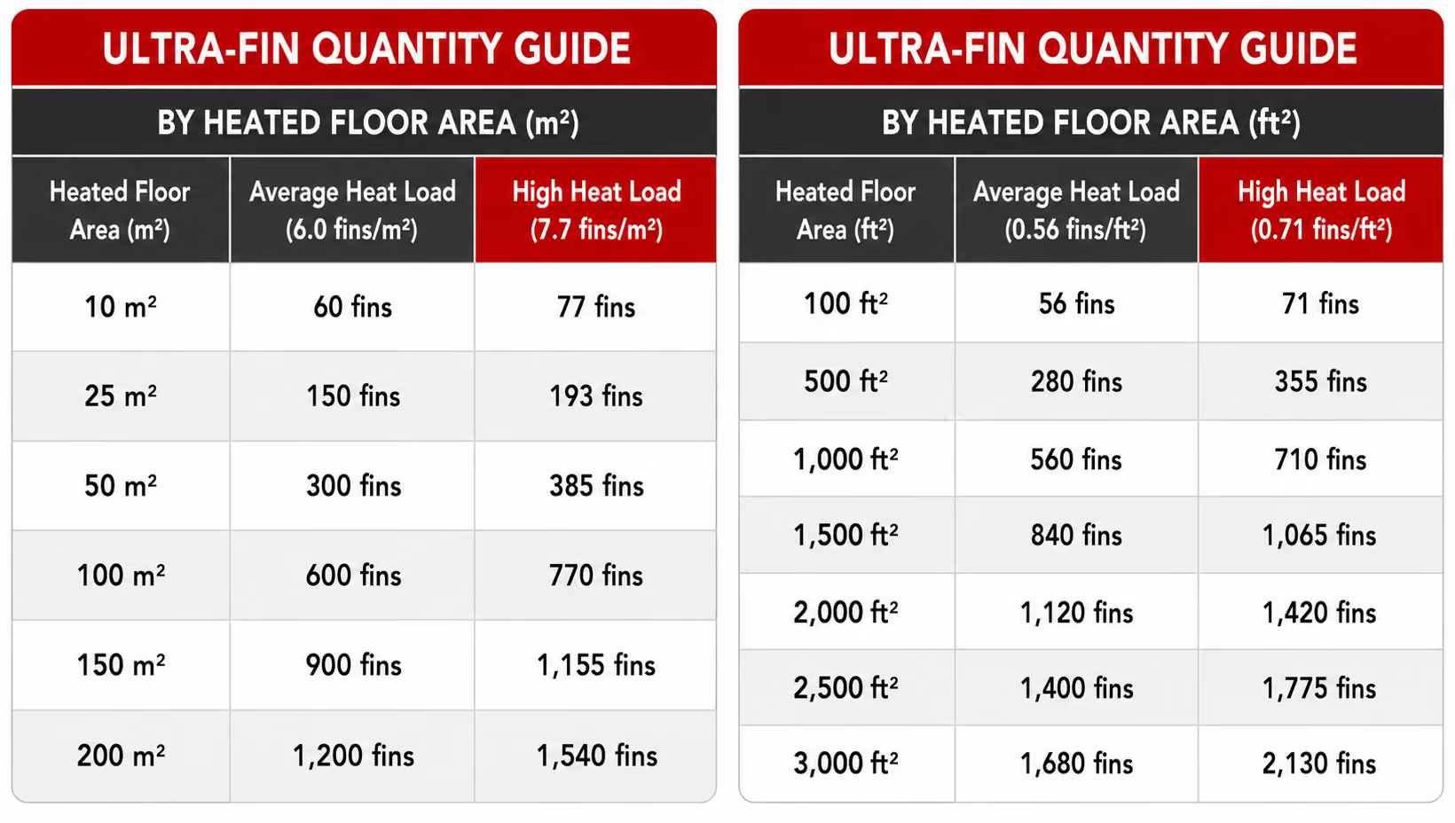
Ultra-Fin performance is optimized by matching fin spacing to the calculated room heat load. Higher heat-loss areas require increased fin density, while lower heat-loss areas can be installed with wider spacing without sacrificing comfort or efficiency.
Use higher Ultra-Fin density when designing for the lowest possible operating water temperature.
HEAT LOAD GUIDE
Design Load
Ultra-Fin Density
Low Load
6 fins/m2 (0.56 fins/ft2)
High Load
7.7 fins/m2 (0.71 fins/ft2)
BEFORE YOU BEGIN
Heat load calculated
Loop lengths verified
Loop lengths verified
Manifold location planned
TUBING GUIDELINES
Use 1/2 in. (16 mm) or 3/4 in. (20 mm) tubing
Keep loops balanced
Verify layout against the calculated heat load
LAYOUT RULES
Space fins based on heat load
Keep loops balanced
Avoid excessive loop length
Maintain consistent tube elevation
SYSTEM SUMMARY
ITEM
REQUIREMENT
Tubing
1/2" (16 mm) or 3/4" (20 mm)
Spacing
Based on calculated heat load
Water Temp
100–180°F (38–82°C)
Insulation
Continuous below joists
Tubing Elevation
Maintain consistent elevation
SYSTEM SUMMARY
CRITICAL DESIGN NOTE
If future conversion from a boiler to an air-to-water heat pump is anticipated, design the Ultra-Fin system using increased fin density (higher-load spacing) from the outset. The additional heat transfer surface allows the system to deliver the required heat output while operating at the lowest practical water temperature, maximizing efficiency today and ensuring compatability with future low-temperature heat sources.
Quick Calculation Reference
Layout and Spacing Guide
Use these quick references for planning. Final layouts and material lists can be generated with the Ultra‑Calc™
Tubing Quantity
Tubing quantity depends on joist spacing, installation method, and designheat load. Use the Ultra‑Calc™ software or the tubing layout tables in the manual to estimate the required tubing length for your project. Allow additional tubing for manifold connections and field routing where required.
MAXIMUM LOOP LENGTH
300 ft
(91 m) per loop
Maintain balanced loops
Avoid excessive circuit length
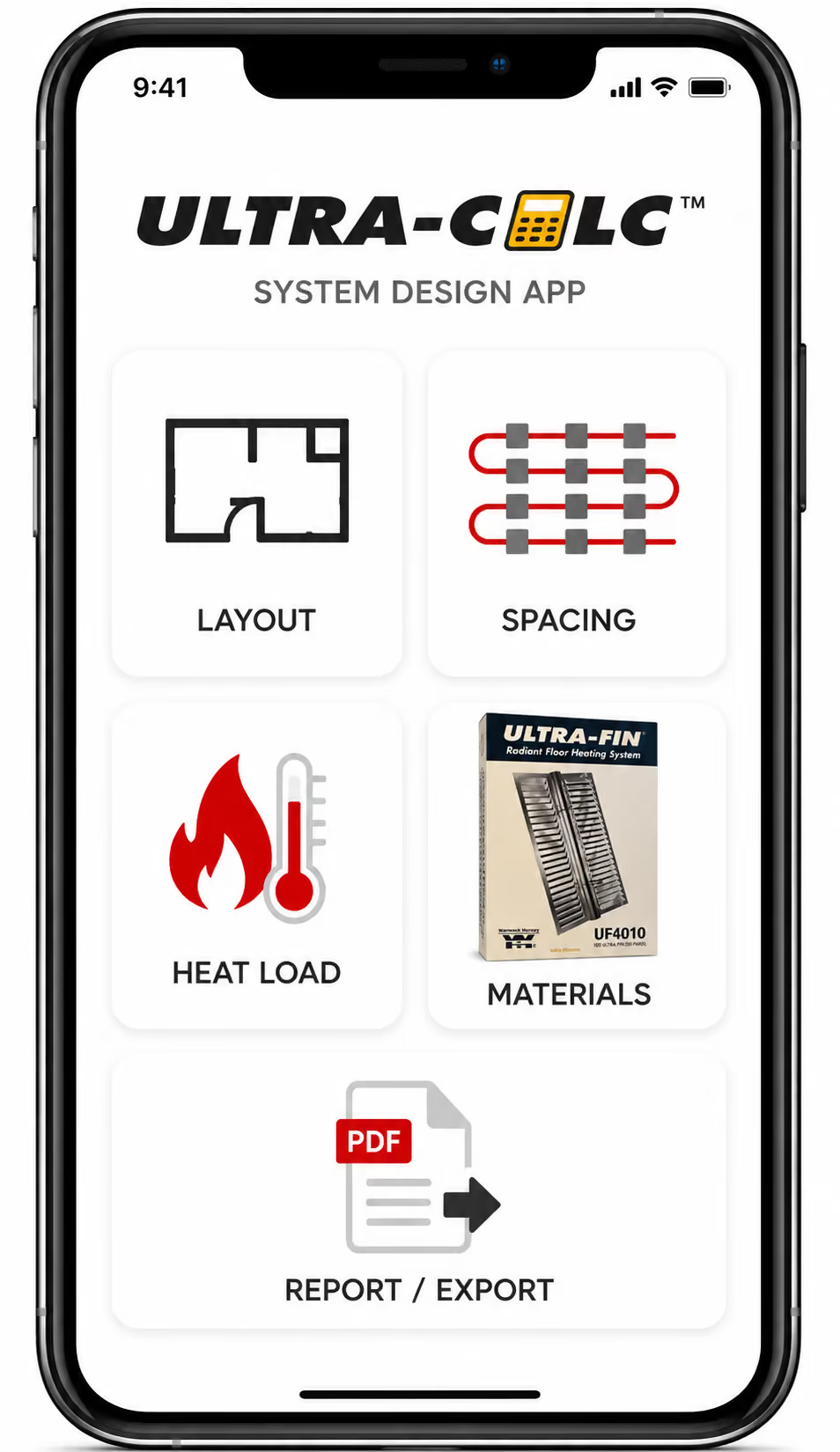
Free Online Design Tool
Ultra-Calc System Design Tool
Ultra‑Calc™ is a free online design tool that generates complete system layouts, material quantities, and project documentation, and printable reports in minutes.
What Ultra-Calc does
Calculates Ultra-Fin spacing
Calculates tubing quantity
Optimizes for joist spacing
Calculates design heat load
Generates complete material list
Exports professional PDF reports
Design Inputs
JOIST SPACING
INSTALLATION METHOD
HEAT LOAD
SYSTEM TYPE
IMPORTANT NOTE
When designing for future air‑to‑water heat pump compatability, select higher-density from the outset
Lower operating water temperatures
Improved system efficiency
Faster heat transfer response